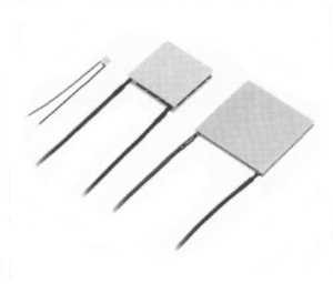
Peltier heat pumps
Introduction of the Peltier effect
In 1834 Jean C.A.Peltier discoverd that the passage of an electric current through the junction of two dissimilar conductors can either cool or heat this junction depending on the direction of current.  Heat generation of absorption rates are proportional tot the magintude of the current and also the temperature of the juntion.
Practical Peltier Effect Heat Pumps consist of many such couples connected electrically in series and thermally in parallel.
Semiconductors doped both p and n form the elements of the couple and are soldered to copper connecting strips.  Ceramic faceplates electrically insulate these connecting strips from external surfaces.  The semiconductor material used is bismuth telluride as this shows the most pronounced affect at moderate operating temperatures.
At open circuit a temperature gradient maintained across the device creates a potential across its teminals proportional to the temperature ndifference.  If teh temperature difference is maintained, and if the device is connected to an electrical load power is generated.
If, instead the device is connected to a DC source, heat will be absorbed to one end of the device, cooling itn while heat rejected at the other endn where the temperature rises.  Reversing the current reverses the flow of heat.  Therefore the module can generate electric power or, depending on how it is connected to external circuitry, heat or cool an object.

A common misconception is that the Peltier device somehow absorbs heat and carries it away, perhaps with the electric current.  This simply not true.  Yhe device only transfers or pumps heat from one of its sides to the opposite side.  At the hot side, the heat must be removed through the use of a heat sink or by some other means.  It is important to realise that the heat deliverd to the hot side of the device includes the pumped heat plus the electrical power dissipated within the device.
Installation of Peltier devices
Peltier devices are only as strong as the semiconductor materials used in their fabvrication and thus may be damaged by the application of excessive stress.  Modules should never be designed as a mechanical supporting member of an assembly

Two mounting methods are recommended with the clamping method being generally preferred.  Epoxy bonding should not be used when operation in the vacuum is required.
Power Supply considerations
Peltier devices operate from direct current and the power requirements are usually not stringent or precise.  For most applications, unreagulated dc power with a ripple contnet of 10% or less is satisfactory and it is possible that higher levels of ripple can be tolerated for certain non-critical applications.  However, because this ripple will degrade module performance it is generally recommended that ripple component be limited to 10% or less.
We are using a NiCd battery as power supply for our Peltier in the modified Connectix grayscale webcam.
The Peltier device i'm using for cooling the TC255P CCD chip is cooled with a small Peltier device of 8mmx12mm.
I have got it from a colleague.  I dont know the type or manufacturer of this Peltier device.  So, i made some tests with this device.  I have connected the Peltier on a laboratory power supply and measured the voltage, current, cold and hot temperature.  I have found that the Peltier device can work with one NiCd battery of 1.2V 4000 mAh.
For a delta temperature of 50 degrees Celcius i'll need a current of 2 A and aprox. 1 V.
Using Peltier devices
When trying to determine the heat pumping capacity required, two factors must be considered; active heating elements and heat leak.
Active heating elements are any components which have a power consumption. All of this power consumption (input power) will eventually converted to heat and should be considered as heat load.
An object that is held at a temperature below ambient will draw heat from the surroundings onto its cold surface. The result of this additional heat is that a cooled object which is not insulated will not be able to maintain temperatures as low as one which has insulation. The additional heat load requirement is called the heat leak.  Three factors affect the magnitude of the heat leak. These are:
There are other sources of heat leak such as conductions heat from electrical wires or heat leak from the heat sink back to the cold plate of the Peltier device.  Hence precice calculation of heat leak is difficult and it may be best determined emperically.
Choosing the proper heat sink
Once the required heat pumping capacity hes been determined the next step is choosing the proper heat sink.  A Peltier device is not a sponge which absorbs heat, rather, it is a heat pump.  The heat which is pumped out of the cold surface is deposited on the hot side of the module.  This heat must be dissipated in some way. If it is not the hot side of the device will heat up to the point where it will stop functioning as a cooling device and actually begin to heat the cold surface.
From fundamentals, a heat sink must be maintained at a temperature higher than ambient to transfer heat from its surface out into the surroundings.  The higher the heatsink temperature above the ambient temperature the more heat can be transferred out of the heatsink.  This point to choosing a heat sink will get as hot as possible.  However, reference to the performance curves shows that as the delta-T across the module becomes larger (as result of the increased hot side temperature) the heat pumping capacity and the coefficient of performance both decrease.  Cinsidering both these phenomena a heat sink which rises to a temperature between 5 and 15° celcius above ambient is a practical choice.
How to use universal performance graphs
example:
a device dissipates 31 watts of power.  It is desired to maintain the device at a constant temperature of +5°C, the ambient temperature being +35 °C (ie Tc=+5°C, Th=+35°C). To select the appriopate module, approach with the following method:
delta-T = Th-Tc or = +35-5°c= +30°C

Choose operating current (typically from 30G to 40G at 35G(equals 35/50=70% of Imax.)

From Th=+35°C graph (delta-T= +30°, I=35G), obtain Qc/GXN=1.65, Then GXN=Qc/1.65 = 31/1.65 = 18.8

Choose module with G X N > 18.8

This implies that a 68.8W module the most suitable for the application.
Manufacturers of Peltier devices:
Read here more about assembling Peltier devices
  • The mounting surfaces should be smooth to within 0.001 in.
  • Clean the module and mounting surfaces to remove burrs,grit, etc.
  • Coat the module hot side with a thin film of heatsink compound and place the module on the heat sink. Applying firm but even downward pressure, rock the module from side to side until a slight resistance is felt an excess heatsink compound is squeezed out.
  • Coat the cold side of the module with a thin film of heatsink compound.  Place the object to be cooled in contact with the module and rock the object slightly from side to side to squeeze out excess thermal grease.
  • Both the object to be cooled and the heatsink together using either stainless steel screws with spring washers or nylon screws.  To ensure even pressure across the module surfaces, thighten all screws finger thight and then continue tightening in an alternate or diagonal pattern starting with the centre screws (if any) first.  Maximum recommended compression loading is 15 pounds per square inch of module surface. Do not over tighten.
  • The temperature difference betweenambient and the cooling device.
  • The surface area of the cooled device.
  • The amount of insulation used. It is advantageous to termally insulate the device being cooled in order to reduce the heat leak to minimum.
Melcor
Marlow Peltier